200-301 Practice Questions
Implementing and Administering Cisco Solutions (200-301 CCNA) v1.1
Last Update 3 days ago
Total Questions : 1242
Dive into our fully updated and stable 200-301 practice test platform, featuring all the latest CCNA exam questions added this week. Our preparation tool is more than just a Cisco study aid; it's a strategic advantage.
Our free CCNA practice questions crafted to reflect the domains and difficulty of the actual exam. The detailed rationales explain the 'why' behind each answer, reinforcing key concepts about 200-301. Use this test to pinpoint which areas you need to focus your study on.

Which design element is a best practice when deploying an 802.11b wireless infrastructure?
Refer to the exhibit.
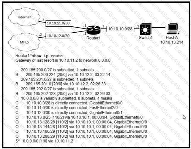
Which prefix does Router 1 use for traffic to Host A?
How do AAA operations compare regarding user identification, user services and access control?
What is the effect when loopback interfaces and the configured router ID are absent during the OSPF Process configuration?
What is the primary different between AAA authentication and authorization?
Refer to the exhibit.
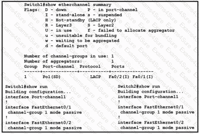
Which change to the configuration on Switch?
allows the two switches to establish an EtherChannel?
Refer to the exhibit.
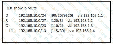
How does router R1 handle traffic to 192.168.10.16?
Which statement correctly compares traditional networks and controller-based networks?
What is the path for traffic sent from one user workstation to another workstation on a separate switch In a three-tier architecture model?
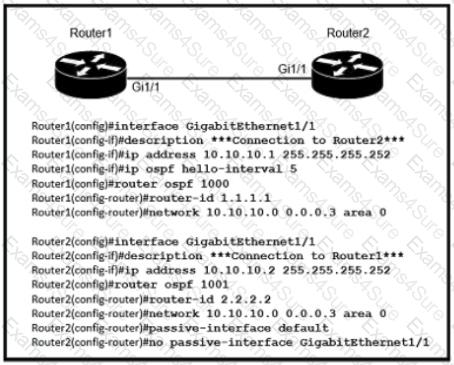
Refer to the exhibit. After the configuration is applied, the two routers fail to establish an OSPF neighbor relationship. what is the reason for the problem?
Refer to the exhibit.
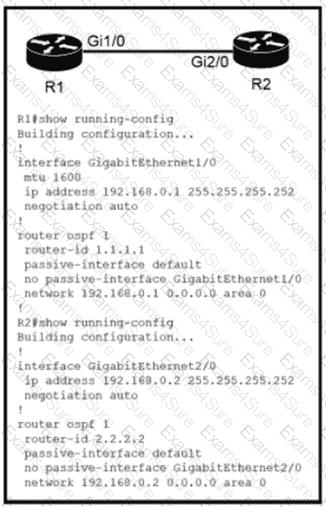
Which configuration issue is preventing the OSPF neighbor relationship from being established between the two routers?
Refer to the exhibit.
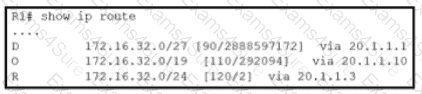
Router R1 is running three different routing protocols. Which route characteristic is used by the router to forward the packet that it receives for destination IP 172.16.32.1?
Refer to the exhibit.
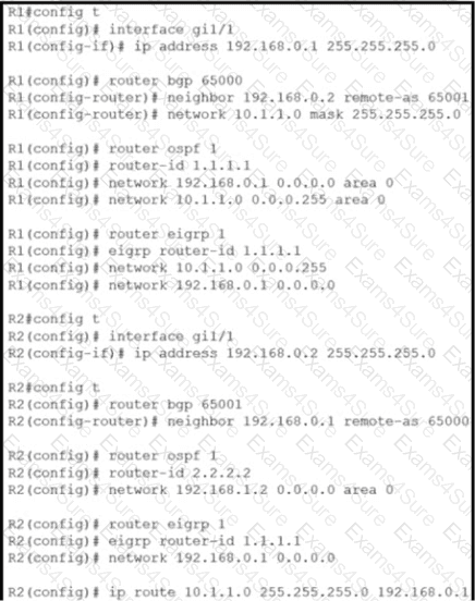
Router R2 is configured with multiple routes to reach network 10 1.1 0/24 from router R1. What protocol is chosen by router R2 to reach the destination network 10.1 1 0/24?
Which IPv6 address type provides communication between subnets and is unable to route on the Internet?
Which statement about Link Aggregation when implemented on a Cisco Wireless LAN Controller is true?
Refer to Exhibit.
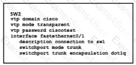
How does SW2 interact with other switches in this VTP domain?
When a site-to-site VPN is configured, which IPsec mode provides encapsulation and encryption of the entire original IP packet?
An engineer needs to add an old switch back into a network. To prevent the switch from corrupting the VLAN database which action must be taken?
Which resource is able to be shared among virtual machines deployed on the same physical server?