
Refer to the exhibit.
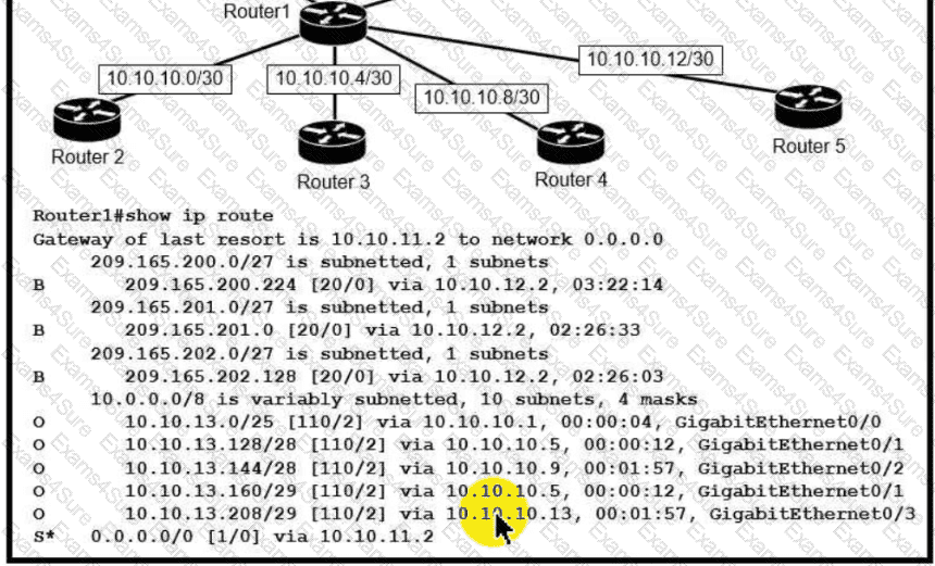
Which next-hop IP address does Routed use for packets destined to host 10 10.13.158?
A network engineer is replacing the switches that belong to a managed-services client with new Cisco Catalyst switches. The new switches will be configured for updated security standards, including replacing Telnet services with encrypted connections and doubling the modulus size from 1024. Which two commands must the engineer configure on the new switches? (Choose two.)
Refer to the exhibit.
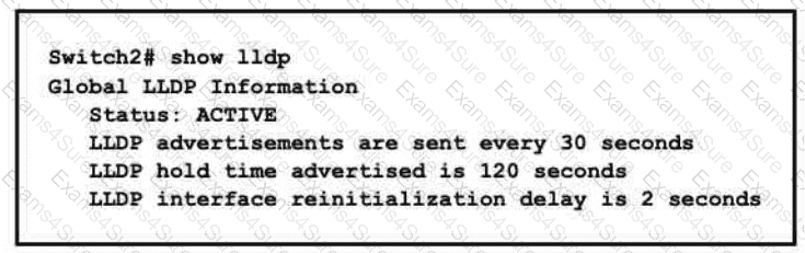
A network engineer must update the configuration on Switch2 so that it sends LLDP packets every minute and the information sent via LLDP is refreshed every 3 minutes Which configuration must the engineer apply?
A)

B)

C)
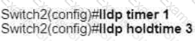
D)

Refer to the exhibit.
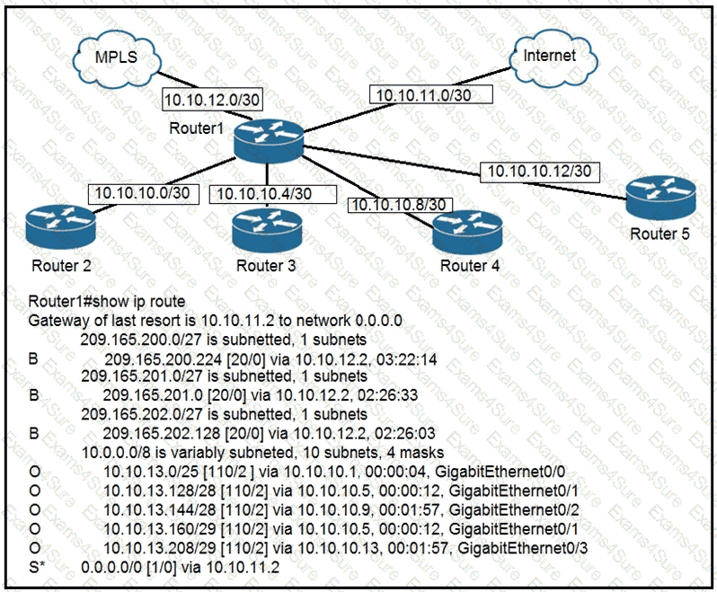
To which device does Router1 send packets that are destined to host 10.10.13.165?
A network engineer must create a diagram of a multivendor network. Which command must be configured on the Cisco devices so that the topology of the network can be mapped?
Router A learns the same route from two different neighbors, one of the neighbor routers is an OSPF neighbor and the other is an EIGRP neighbor. What is the administrative distance of the route that will be installed in the routing table?
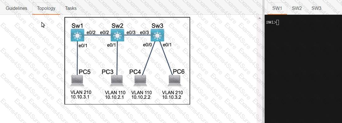
Three switches must be configured for Layer 2 connectivity. The company requires only the designated VLANs to be configured on their respective switches and permitted accross any links between switches for security purposes. Do not modify or delete VTP configurations.
The network needs two user-defined VLANs configured:
VLAN 110: MARKETING
VLAN 210: FINANCE
1. Configure the VLANs on the designated switches and assign them as access ports to the interfaces connected to the PCs.
2. Configure the e0/2 interfaces on Sw1 and Sw2 as 802.1q trunks with only the required VLANs permitted.
3. Configure the e0/3 interfaces on Sw2 and Sw3 as 802.1q trunks with only the required VLANs permitted.
An engineer is configuring router R1 with an IPv6 static route for prefix 2019:C15C:0CAF:E001::/64. The next hop must be 2019:C15C:0CAF:E002::1 The route must be reachable via the R1 Gigabit 0/0 interface. Which command configures the designated route?
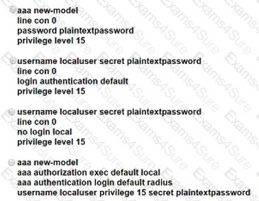
After a recent security breach and a RADIUS failure, an engineer must secure the console port of each enterprise router with a local username and password. Which configuration must the engineer apply to accomplish this task?
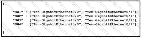
Topology:
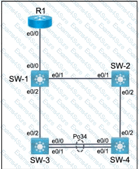
All relevant ports are preconfigured as IEEE 802.1Q trunks.
Task 1
Configure SW-1 port Ethernet0/0 to permit only VLANs 5 and 6.
Task 2
Configure ports Ethernet0/1 on SW-1 and SW-2 to use VLAN 77 as the native VLAN.
Task 3
Configure SW-2 port Ethernet0/2 to permit only VLAN 6.
Task 4
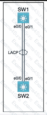
Using LACP, create a Port-Channel between SW-3 and SW-4.
Combine Ethernet0/0 and Ethernet0/1 into a Port-Channel while leaving the existing trunk configurations intact.
Assign Port-Channel number 34.
Only SW-3 must initiate LACP negotiations.
Refer to the exhibit.
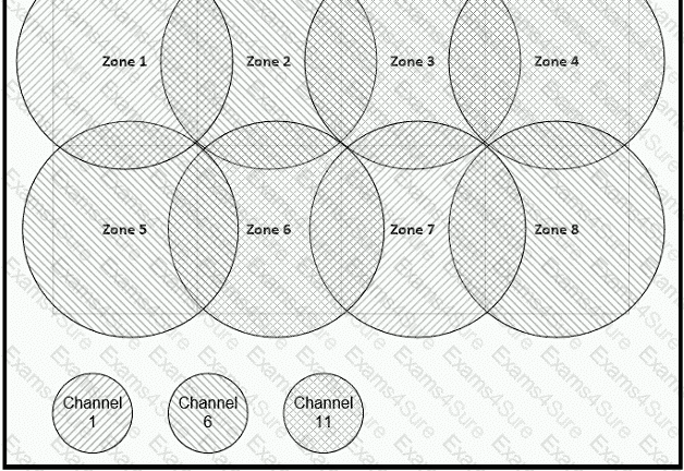
Between which zones do wireless users expect to experience intermittent connectivity?
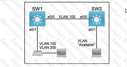
All physical cabling between the two switches is installed. Configure the network connectivity between the switches using the designated VLANs and interfaces.
1. Configure VLAN 100 named Compute and VLAN 200 named Telephony where required for each task.
2. Configure Ethernet0/1 on SW2 to use the existing VLAN named Available.
3. Configure the connection between the switches using access ports.
4. Configure Ethernet0/1 on SW1 using data and voice VLANs.
5. Configure Ethemet0/1 on SW2 so that the Cisco proprietary neighbor discovery protocol is turned off for the designated interface only.
Physical connectivity is implemented between the two Layer 2 switches,
and the network connectivity between them must be configured.
I . Configure an LACP EtherChanneI and number it as 44; configure it
between switches SWI and SW2 using interfaces EthernetO/O and
Ethernet0/1 on both sides. The LACP mode must match on both ends.
2. Configure the EtherChanneI as a trunk link.
3. Configure the trunk link with 802. Iq tags.
4. Configure VLAN ' MONITORING ' as the untagged VLAN of the
EtherChannel.
==================
Guidelines
This is a lab item in which tasks will be performed on virtual devices.
• Refer to the Tasks tab to view the tasks for this lab item.
• Refer to the Topology tab to access the device console(s) and perform the tasks.
• Console access is available for all required devices by clicking the device icon or using
the tab(s) above the console window.
• All necessary preconfigurations have been applied.
• Do not change the enable password or hostname for any device.
• Save your configurations to NVRAM before moving to the next item.
• Click Next at the bottom of the screen to submit this lab and move to the next question.
• When Next is clicked, the lab closes and cannot be reopened.
All physical cabling is in place. A company plans to deploy 32 new sites.
The sites will utilize both IPv4 and IPv6 networks.
1 . Subnet 172.25.0.0/16 to meet the subnet requirements and maximize
the number of hosts
Using the second subnet
• Assign the first usable IP address to e0/0 on Sw1O1
• Assign the last usable IP address to e0/0 on Sw102
2. Subnet to meet the subnet requirements and maximize
the number of hosts
c Using the second subnet
• Assign an IPv6 GUA using a unique 64-Bit interface identifier
on e0/0 on Sw101
• Assign an IPv6 GUA using a unique 64-Bit interface identifier
on eO/O on swi02
Guidelines
This is a lab item in which tasks will be performed on virtual devices.
• Refer to the Tasks tab to view the tasks for this lab item.
• Refer to the Topology tab to access the device console(s) and perform the tasks.
• Console access is available for all required devices by clicking the device icon or using
the tab(s) above the console window.
• All necessary preconfigurations have been applied.
• Do not change the enable password or hostname for any device.
• Save your configurations to NVRAM before moving to the next item.
• Click Next at the bottom of the screen to submit this lab and move to the next question.
• When Next is clicked, the lab closes and cannot be reopened.

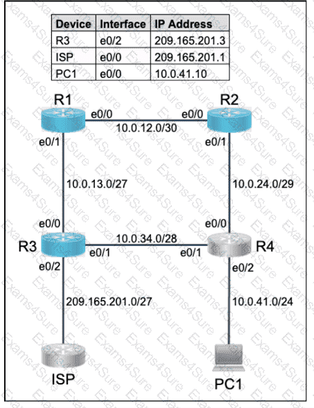
All physical cabling is in place. Router R4 and PCI are fully configured and
inaccessible. R4 ' s WAN interfaces use .4 in the last octet for each subnet.
Configurations should ensure that connectivity is established end-to-end.
1 . Configure static routing to ensure RI prefers the path through R2 to
reach only PCI on R4 ' s LAN
2. Configure static routing that ensures traffic sourced from RI will take
an alternate path through R3 to PCI in the event of an outage along
the primary path
3. Configure default routes on RI and R3 to the Internet using the least number of hops
Guidelines
This is a lab item in which tasks will be performed on virtual devices.
• Refer to the Tasks tab to view the tasks for this lab item.
• Refer to the Topology tab to access the device console(s) and perform the tasks.
• Console access is available for all required devices by clicking the device icon or using
the tab(s) above the console window.
• All necessary preconfigurations have been applied.
• Do not change the enable password or hostname for any device.
• Save your configurations to NVRAM before moving to the next item.
• Click Next at the bottom of the screen to submit this lab and move to the next question.
• When Next is clicked, the lab closes and cannot be reopened.
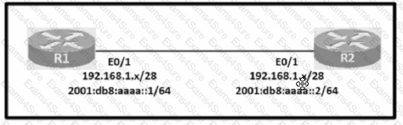
Configure IPv4 and IPv6 connectivity between two routers. For IPv4, use a /28 network from the 192.168.1.0/24 private range. For IPv6, use the first /64 subnet from the 2001:0db8:aaaa::/48 subnet.
1. Using Ethernet0/1 on routers R1 and R2, configure the next usable/28 from the 192.168.1.0/24 range. The network 192.168.1.0/28 is unavailable.
2. For the IPv4 /28 subnet, router R1 must be configured with the first usable host address.
3. For the IPv4 /28 subnet, router R2 must be configured with the last usable host address.
4. For the IPv6 /64 subnet, configure the routers with the IP addressing provided from the topology.
5. A ping must work between the routers on the IPv4 and IPv6 address ranges.
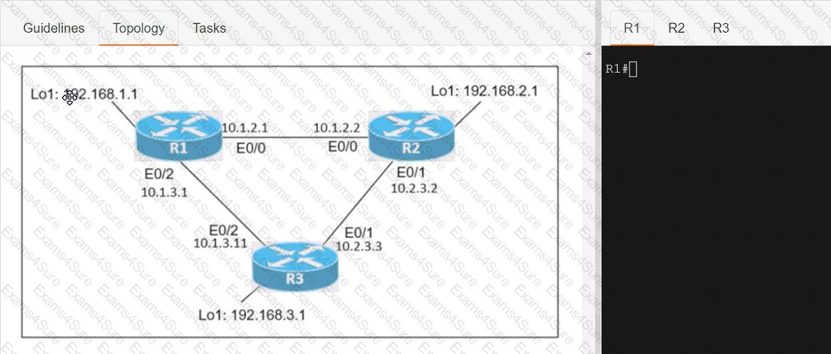
Connectivity between three routers has been established, and IP services must be configured jn the order presented to complete the implementation Tasks assigned include configuration of NAT, NTP, DHCP, and SSH services.
1. All traffic sent from R3 to the R1 Loopback address must be configured for NAT on R2. All source addresses must be translated from R3 to the IP address of Ethernet0/0 on R2, while using only a standard access list named NAT To verify, a ping must be successful to the R1 Loopback address sourced from R3. Do not use NVI NAT configuration.
2. Configure R1 as an NTP server and R2 as a client, not as a peer, using the IP address of the R1 Ethernet0/2 interface. Set the clock on the NTP server for midnight on January 1, 2019.
3. Configure R1 as a DHCP server for the network 10.1.3.0/24 in a pool named TEST. Using a single command, exclude addresses 1-10 from the range. Interface Ethernet0/2 on R3 must be issued the IP address of 10.1.3.11 via DHCP.
4. Configure SSH connectivity from R1 to R3, while excluding access via other remote connection protocols. Access for user root and password Cisco must be set on router R3 using RSA and 1024 bits. Verify connectivity using an SSH session from router R1 using a destination address of 10.1.3.11. Do NOT modify console access or line numbers to accomplish this task.
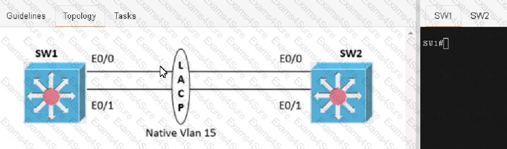
Physical connectivity is implemented between the two Layer 2 switches, and the network connectivity between them must be configured
1. Configure an LACP EtherChannel and number it as 1; configure it between switches SW1 and SVV2 using interfaces Ethernet0/0 and Ethernet0/1 on both sides. The LACP mode must match on both ends
2 Configure the EtherChannel as a trunk link.
3. Configure the trunk link with 802.1 q tags.
4. Configure the native VLAN of the EtherChannel as VLAN 15.
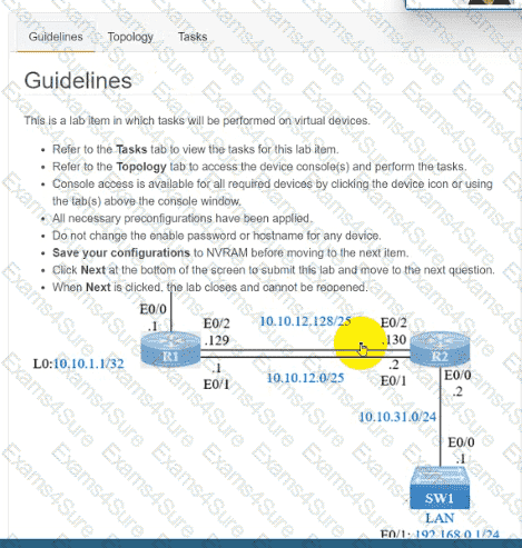
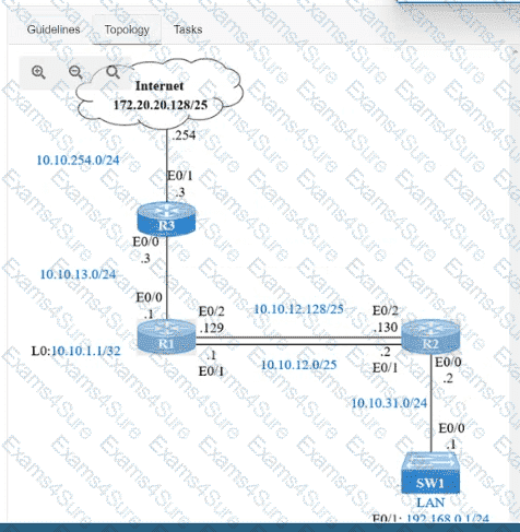
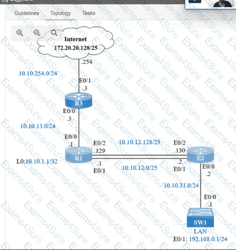
IP connectivity and OSPF are preconfigured on all devices where necessary. Do not make any changes to the IP addressing or OSP
F.
The company policy uses connected interfaces and next hops when configuring static routes except for load balancing or redundancy without floating static. Connectivity must be established between subnet 172.20.20.128/25 on the Internet and the LAN at 192.168.0.0/24 connected to SW1:1. Configure reachability to the switch SW1 LAN subnet in router R2.
2. Configure default reachability to the Internet subnet in router R1.
3. Configure a single static route in router R2 to reach to the Internet subnet considering both redundant links between routers R1 and R2. A default route is NOT allowed in router R2.
4. Configure a static route in router R1 toward the switch SW1 LAN subnet where the primary link must be through Ethernet0/1. and the backup link must be through Ethernet0/2 using a floating route. Use the minimal administrative distance value when required.